- Lab Chart Reader For Mac How To Measure Amplitude
- Lab Chart Reader For Mac How To Measure Amplitude Free
- Lab Chart Reader For Mac How To Measure Amplitude &
The MLS310/8 Heart Rate Variability (HRV) Module Version 8 for Windows and MAC provides a comprehensive set of tools for the analysis and display of variation in the interval between heartbeats in human and animal electrocardiogram recordings. Electrocardiograms or other heartbeat-related signals can be recorded using the PowerLab data acquisition system and changes in the heart rate can be. 'Audio Frequency Analyzer' is a powerful real-time audio analyzer (RTA) app for iPhone. This app can measure the frequency response in 30 split band scale of 1/3 octave in real time. Also it can be displayed the FFT analysis result. 'Audio Frequency Analyzer' is available in a variety of applic. Expression (applies formulas to images), HPGL Reader, Warp, OpenGL Example, PxM Reader (imports PBM, PGM and PPM), Pixellate, Seam Carving, Animated PNG (APNG) Writer Bob Dougherty Ellipse ROI, Live Histogram, Measure Stack, Multi Measure, NTSC DV2Float, QuickTime Grab, Layers, Stack Sorter, Measure.
Last week, I had you print out a form that showed the VHF and UHF bands and mark down any of the television stations that could cause interference from TV Fool and a White Space Database. In doing this you have a road map to the wireless spectrum to start off with! Today, I want to talk about a few essential tools that will help you find the exact spots in the VHF and UHF bands to place your wireless channels. Not only will it help you place them, but it will also help test and troubleshoot most wireless problems that you will face in the future! These tools are Inexpensive RF Spectrum Analyzers!
- It can be displayed by running a BNC cable from AFG Out, which is on the back panel, to one of the analog channels on the front panel. Channel One is the default selection. The plan is to input two sine waves into separate channels, with the capability of changing amplitude and frequency, and to view the Lissajous pattern in the scope’s XY mode.
- An amplitude or frequency modulated carrier wave from the transmitter causes current to flow in the receiver antenna. In the tuner, a variable capacitor or electronic tuning circuitry singles out the desired frequency, and this modulated RF signal is amplified and conveyed to a mixer, which is also connected to a local (in receiver) oscillator.
My goal for this series on the Wireless Microphone Frequency Selection was to really make understanding the technical aspect of wireless systems obtainable. I have heard from many of you thanking me for breaking this up into a few different parts. When learning all of the aspects of wireless systems, reading all of the blog posts in one sitting is a LOT to process at one time. So, I encourage you to take these posts in small chunks so that you can really get a firm understanding. The technical aspect of wireless systems will really make or break it for your church/venue in the future.
If you haven’t started at the beginning of my series, I would suggest that you start with this post first: Wireless Microphone Frequency Selection – How to make or BREAK your wireless system!!
The RF Spectrum Analyzer
As audio engineers, we have seen audio spectrum analyzers in the form of RTA’s (Real-Time Analyzer), spectrographs, and even FFT transfer function software. Some of these include the main players like Smaart, SATLive, Easera and Meyer SIM; but also include some inexpensive programs such as TrueRTA. Spectrum analyzers also exist in the radio frequency spectrum as well but typically these pieces of hardware are upwards of several thousand dollars. While that can be an easy and smart purchase for large churches and venues, that is not practical for most churches, venues or volunteers.
Inexpensive Radio Spectrum Analyzers
There are some amazing inexpensive radio frequency spectrum analyzers on the market. Below are two of my favorites!
RF Explorer – $129
The RF Explorer was created by Ariel Rocholl and is a handheld RF spectrum analyzer for $129!! What I love about this item is that the RF Explorer WSUB1G is only $129 and has a frequency range from 240MHz-960MHz. It can measure and display live, at one time, a frequency span of 112kHz-300MHz with a resolution of 0.5dBm in amplitude and 1kHz in frequency. (Make sure to update it to the latest firmware as the older firmware has a frequency span of 112kHz-100MHz)
Charged over a USB connection to your computer it is portable and easily tossed into your bag of tools to grab when you need it. You can also combine the RF Explorer with a computer with free software to have the ability to record the RF spectrum analysis and have more functionality.
This is the tool that I used when testing and documenting using television coaxial splitters as a DIY wireless microphone distribution. You can check out that video on YouTube here if you haven’t already!
One thing to note is that the RF Explorer has a few other models that cover the 15MHz-2700MHz, 4.85GHz-6.1GHz, a WiFi model that covers 2.4GHz and 5GHz, and even a Signal Generator model!
RTL-SDR RTL2832U Dongle – $20!
The RTL2832U and R820T2 chip based USB dongles are by far the CHEAPEST option for a spectrum analyzer that you can find. These USB dongles are software defined radios (SDR) and instead of using hardware as the primary function, it uses a computer and software to do the main portion of the depicting of RF. RTL-SDR.com has one of the best versions of the dongle which includes an aluminum case for cooling, a more common SMA connector for the antenna and a 1 PPM temperature compensated oscillator which yields accurate tuning and no frequency fluctuation due to temperature change.
The RTL-SDR dongles have a frequency range of 24MHz-1700MHz and can display live, at one time, a frequency span of up to 3.2MHz. Depending on the software you use, you can measure amplitude to the 0.01dBm level of resolution.
Software for RTL-SDR Dongle
As the RTL-SDR dongle is software based, I wanted to show the two different programs that I use with it. Manik bengali movie download.

SDR#
This is one of the main programs to use with the RTL-SDR dongle. You are able to display live up to 3.2MHz at one time, change frequency with your mouse and even listen to a few different modes of modulation including LSB, USB, FM, AM and CW. (Download link: HERE, Install Guide: HERE)
RTLSDR Scanner
Lab Chart Reader For Mac How To Measure Amplitude
When I was trying out the RTL-SDR dongle, I really wanted to have an inexpensive radio spectrum analyzer option for volunteers to purchase but not completely empty their wallets! This is the one program that made this dongle really useful for our use in the wireless system. This software allows you to set a frequency range of say 470MHz-698MHz and it will (slowly) measure the span and display the results on the screen.
While not real-time, this will massively help find what problem frequencies there are at your location. Remember, for $20 and some free software, we have a tool that will let us make very specific measurements in the radio frequency spectrum!
Download Link: HERE, Install Guide: HERE
Using an RF Spectrum Analyzer
Now, I LOVE the RF Explorer and if you can spare the $129 for purchase, it is worth it! Being able to display a frequency span of up to 100MHz at one time LIVE is really useful. Also, not needing to carry around a computer for making measurements is nice. Lastly, this is able to sync into the main program that I am going to be mentioning in future posts!
I am going to dedicate the rest of the post to the RTL-SDR dongle method as I really want to empower those of you who will purchase the inexpensive option. Either option will work, the measurements will be the same no matter which spectrum analyzer you use, just the RTL-SDR will be slower, but cheaper, to come to the final result.
Lab Chart Reader For Mac How To Measure Amplitude Free
Okay, Drew, so you have shown us some tempting tools to go purchase, but how is this going to help me?! The first thing I am going to do is a measurement of the UHF band from 470MHz-698MHz and verify our findings from the worksheet I had you fill out during the last post.
For the first measurement, open up RTLSDR Scanner. Input the settings, Start: 470MHz, Stop: 698MHz, Gain at 15.7dB, Mode: Single, Dwell: 8ms, FFT size: 16. Once you have entered those, press Start!
It will take a minute or two depending on the speed of your computer to display the results, but you should see something like below:
Lab Chart Reader For Mac How To Measure Amplitude &
Congratulations! You have just done a measurement of the entire UHF band available to us for use with our wireless microphones and wireless in-ear monitors!
Now, let’s do a more exact measurement. Input the settings, Start: 470MHz, Stop: 698MHz, Gain at 15.7dB, Mode: Single, Dwell: 1 Sec, FFT size: 512. Press ‘Start’! We have done two things here, changed the ‘Dwell’ which is a setting of how long RTLSDR Scanner will measure on one frequency before moving onto the next, and the higher ‘FFT Size’ gives greater precision to the measurement.
What are we looking at here? The 470Mhz-698MHz is the UHF television spectrum from channel 14 up to channel 51. Each television station is 6MHz is allotted 6MHz of bandwidth. Below is a zoomed in version of a television channel, you can see the large peak on the left, that is the pilot signal.
Now if we get out the worksheet from last week, we can go up and down the UHF band and verify our findings. Depending on your area you might find that some of the ‘strong’ television stations are not very powerful in the measurement. Some might find that there are ‘open channels’ on your worksheet that may have ALOT of little spikes of interference. This can be due to a multitude of different reasons from intermodular distortion, reflections, terrain, and even different wireless devices that are in your region.
Go through on your sheet and verify all of the ‘available’ channels, and if they are clear of any spikes on the spectrum analyzer highlight them with a green highlighter. If there is a channel that has a few little spikes, highlight that in orange. If there happens to be a television station on one of your ‘available’ channels, it is possible that your region has out of date information in the white spaces database. Just mark that channel with a horizontal line and move on!
You now have a complete roadmap for the UHF band for your location! Any channels in green are a perfect place to have your wireless system, any channels in orange will need a bit more investigation before assigning wireless systems to those frequencies. Not only do you know what frequency ranges are available to place wireless systems, but you know where NOT to place your wireless channels! The next step I would take is using RTLSDR Scanner to get a more detailed analysis of the available channels, or take SDRSharp and look in more resolution at those frequencies.
Next week I will tackle intermodular distortion and see why this can be such a large problem for our wireless systems.
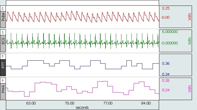
LabChart for Windows 7.3.3 or later includes an arithmeticfunction StepSize() that is designed to facilitate this type of analysis.


To calculate the area of the peak identified, the selectionof the peak can be manually made in the Chart View, and the “Integral Relativeto Baseline” data pad calculation can be used. This calculation is somewhatsensitive to noise fluctuations, and filtering should be used to minimize anyerror that might be induced.

The goal for the StepSize() function is to facilitate themeasurement of amplitude in the situation described by the image above.
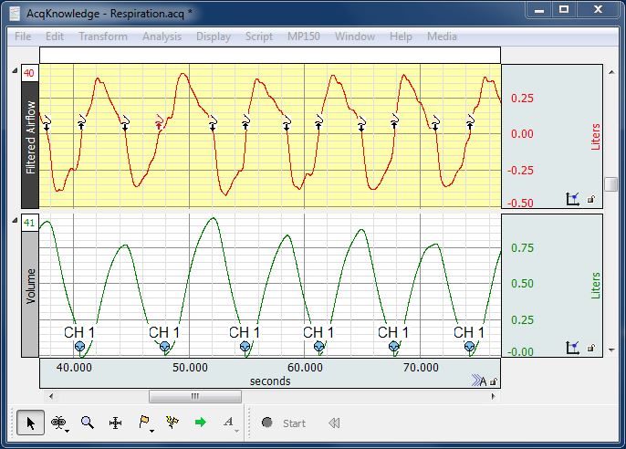
In the image below, Channel 2 is used for the StepsizeCalculation. The StepSize() Arithmetic function outputs a running measurementof the step size calculated from the source waveform. In this example, thefunction StepSize(ch1,0.03,0.02,0.05) is used. The result can be quantified byusing the Data Pad “Minimum Value” function for the same selection made tocalculate the area.
The StepSize() function measures the size of any potentialsteps by performing two non-overlapping linear regressions either side of everypoint in the source waveform.

The format of the function is:
StepSize(source, leftWidth [s], gapWidth [s],rightWidth [s])
- ThegapWidth parameter defaults to 0 s. User%27s manual for kodak easyshare z710.
Xbox one app on mac. - The rightWidth parameter defaults to theleftWidth.
The user can specify the length (in seconds)of the left regression, the gap between the regressions, and the rightregression. The function uses the result of the each regression separately tocalculate the expected value at the mid-point between the two regressions. Theoutput of the function is the expected value from the right regression minusthat from the left regression.
The gap between the regressions should be setnon-zero if the step in the data is not instantaneous. This means the datavalues in the transition will be ignored so that they do not introduce a bias,reducing the measured step magnitude. In this file, the step transition time isbetween 0.02 and 0.03 seconds.


